
Cable HTA CIS Torsadé Souterrain NFC 33-226
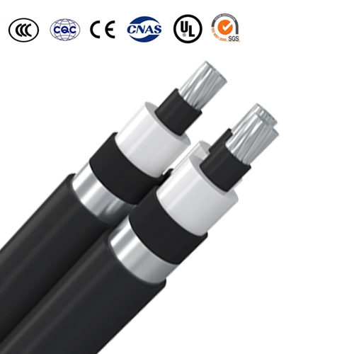
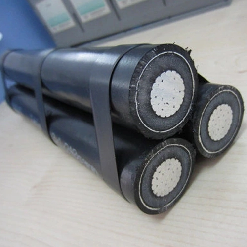
Cable HTA CIS Torsadé Souterrain NFC 33-226
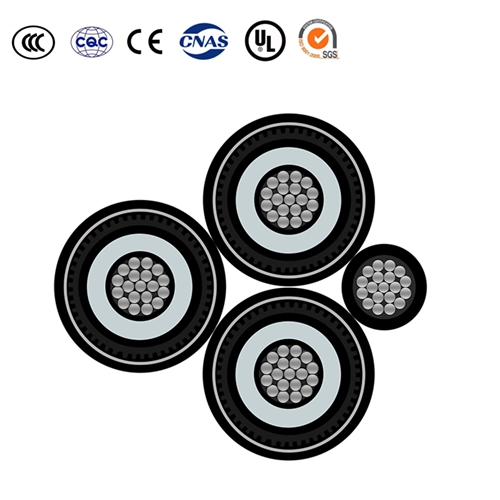
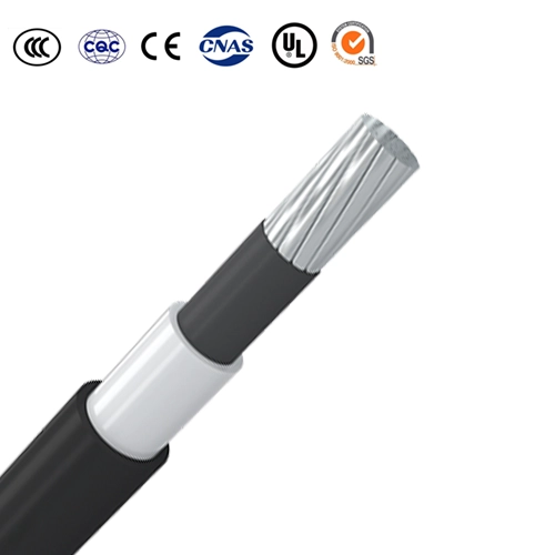
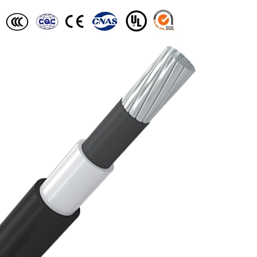
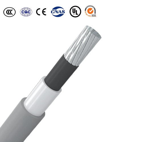
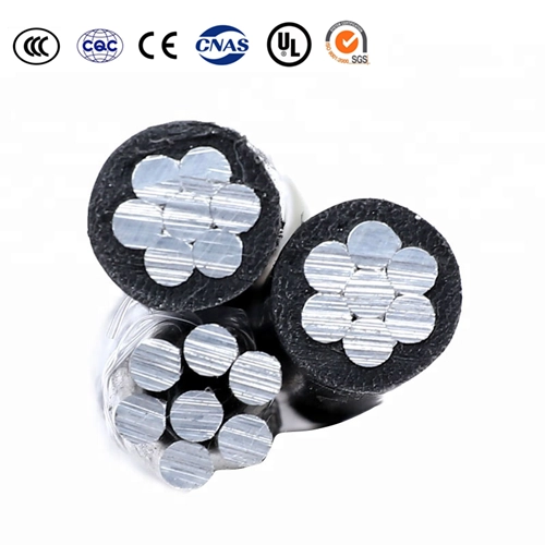
Phase conductor: Aluminum, class 2,circular compacted conductors
Phase conductor screen: Non-metallic,semi-conducting compound
Phase insulation:Cross-linked polyethylene(XLPE)
Phase insulation screen:Non-metallic,semi-conducting compound,extruded strippable grooved elastomer
Phase longitudinal water tightness: Swelling powder
Phase metallic screen: Aluminium plastic tape (AL/PET)
Phase outer sheath: Polyethylene (PE)
Messenger conductor: Stranded galvanized steel wires
Messenger insulation: Polyethylene (PE)Specification
Application
These Cable HTA CIS Torsadé Souterrain NFC 33-226 cables is used for medium voltage public distribution from 6/10kV to 18/30kV. Used for the distribution of electrical energy under normal conditions of overhead installations.
The three phase cable is assembled around a Messenger, which is composed of a steel core with a cross-sectional of 50mm2 and covered insulation with a nominal thickness of 1.2mm.The galvanized steel stranded wire minimum breaking load is 64700N.
●Maximum conductor temperature in normal operation:90˚C.
●Short circuit temperature ( 5 seconds maximum duration ): Shall not exceed 250˚C.
●Ambient installation temperature, range: -10 ~ 50 ˚C.
●Weather resistance: AN3/AF2
●Water proof: AD8
●Mechanical resistance to impacts: AG4
●Minimum bending radius:
During installation:15D,
After installation:10D.
Note:D is overall diameter of cable.
Specifications
● IEC 60228 Conductors of insulate cables
● NFC 33-226 Câbles isolés et leurs accessoires pour réseaux d’énergie Câbles de tensions assignées comprises entre 6/10(12) ● kV et 18/30(36) kV, isolés au polyéthylène réticulé à gradient fixé, pour réseaux de distribution
● IEC 60502-2 Power cables with extruded insulation and their accessories for rated voltages from 1kV(Um=1.2kV) up to 30kV(Um=36kV) – Part 2:Cables for rated voltages of 6kV(Um=7.2kV) and 30kV(Um=36kV)
Parameter
| No. of cores and nominal cross section | Phase | Messenger | Approx. overall diameter | Approx. weight | Max. DC resistance ofconductor at 20℃ |
||||
| Min. Number Ofwires |
Nominal insulation thickness | Nominal AL/PET tape thickness | Nominal sheath thickness |
Conductor | Nominal insulation thickness | ||||
| mm² | No. | mm | mm | mm | No./mm | mm | mm | kg/km | Ω/km |
| 6/10(12)kV | |||||||||
| 3×1×50+1×50 | 6 | 3.4 | 0.20 | 2.0 | 7/3.0 | 1.2 | 49.9 | 1948 | 0.641 |
| 3×1×70+1×50 | 12 | 3.4 | 0.20 | 2.0 | 7/3.0 | 1.2 | 53.6 | 2239 | 0.443 |
| 3×1×95+1×50 | 15 | 3.4 | 0.20 | 2.0 | 7/3.0 | 1.2 | 57.5 | 2579 | 0.320 |
| 3×1×120+1×50 | 15 | 3.4 | 0.20 | 2.0 | 7/3.0 | 1.2 | 60.0 | 2859 | 0.253 |
| 3×1×150+1×50 | 15 | 3.4 | 0.20 | 2.0 | 7/3.0 | 1.2 | 63.3 | 3182 | 0.206 |
| 3×1×185+1×50 | 30 | 3.4 | 0.20 | 2.0 | 7/3.0 | 1.2 | 67.0 | 3599 | 0.164 |
| 3×1×240+1×50 | 30 | 3.4 | 0.20 | 2.0 | 7/3.0 | 1.2 | 71.9 | 4233 | 0.125 |
| 3×1×300+1×50 | 30 | 3.4 | 0.20 | 2.0 | 7/3.0 | 1.2 | 76.7 | 4889 | 0.100 |
| 3×1×400+1×50 | 53 | 3.4 | 0.20 | 2.2 | 7/3.0 | 1.2 | 83.4 | 5852 | 0.0778 |
| 3×1×500+1×50 | 53 | 3.4 | 0.20 | 2.2 | 7/3.0 | 1.2 | 90.9 | 6991 | 0.0605 |
| 3×1×630+1×50 | 53 | 3.4 | 0.20 | 2.4 | 7/3.0 | 1.2 | 99.8 | 8505 | 0.0469 |
| 8.7/16(17.5)kV | |||||||||
| 3×1×50+1×50 | 6 | 4.5 | 0.20 | 2.0 | 7/3.0 | 1.2 | 55.1 | 2220 | 0.641 |
| 3×1×70+1×50 | 12 | 4.5 | 0.20 | 2.0 | 7/3.0 | 1.2 | 58.8 | 2528 | 0.443 |
| 3×1×95+1×50 | 15 | 4.5 | 0.20 | 2.0 | 7/3.0 | 1.2 | 62.6 | 2888 | 0.320 |
| 3×1×120+1×50 | 15 | 4.5 | 0.20 | 2.0 | 7/3.0 | 1.2 | 65.2 | 3181 | 0.253 |
| 3×1×150+1×50 | 15 | 4.5 | 0.20 | 2.0 | 7/3.0 | 1.2 | 68.5 | 3520 | 0.206 |
| 3×1×185+1×50 | 30 | 4.5 | 0.20 | 2.0 | 7/3.0 | 1.2 | 72.1 | 3956 | 0.164 |
| 3×1×240+1×50 | 30 | 4.5 | 0.20 | 2.1 | 7/3.0 | 1.2 | 77.5 | 4648 | 0.125 |
| 3×1×300+1×50 | 30 | 4.5 | 0.20 | 2.1 | 7/3.0 | 1.2 | 82.3 | 5329 | 0.100 |
| 3×1×400+1×50 | 53 | 4.5 | 0.20 | 2.2 | 7/3.0 | 1.2 | 88.6 | 6292 | 0.0778 |
| 3×1×500+1×50 | 53 | 4.5 | 0.20 | 2.3 | 7/3.0 | 1.2 | 96.6 | 7509 | 0.0605 |
| 3×1×630+1×50 | 53 | 4.5 | 0.20 | 2.4 | 7/3.0 | 1.2 | 105.0 | 9027 | 0.0469 |
| 12/20(24)kV | |||||||||
| 3×1×50+1×50 | 6 | 5.5 | 0.20 | 2.0 | 7/3.0 | 1.2 | 59.8 | 2490 | 0.641 |
| 3×1×70+1×50 | 12 | 5.5 | 0.20 | 2.0 | 7/3.0 | 1.2 | 63.5 | 2816 | 0.443 |
| 3×1×95+1×50 | 15 | 5.5 | 0.20 | 2.0 | 7/3.0 | 1.2 | 67.4 | 3193 | 0.320 |
| 3×1×120+1×50 | 15 | 5.5 | 0.20 | 2.0 | 7/3.0 | 1.2 | 70.0 | 3499 | 0.253 |
| 3×1×150+1×50 | 15 | 5.5 | 0.20 | 2.0 | 7/3.0 | 1.2 | 73.2 | 3853 | 0.206 |
| 3×1×185+1×50 | 30 | 5.5 | 0.20 | 2.0 | 7/3.0 | 1.2 | 76.9 | 4306 | 0.164 |
| 3×1×240+1×50 | 30 | 5.5 | 0.20 | 2.1 | 7/3.0 | 1.2 | 82.3 | 5022 | 0.125 |
| 3×1×300+1×50 | 30 | 5.5 | 0.20 | 2.2 | 7/3.0 | 1.2 | 87.5 | 5763 | 0.100 |
| 3×1×400+1×50 | 53 | 5.5 | 0.20 | 2.3 | 7/3.0 | 1.2 | 93.7 | 6756 | 0.0778 |
| 3×1×500+1×50 | 53 | 5.5 | 0.20 | 2.4 | 7/3.0 | 1.2 | 101.7 | 8014 | 0.0605 |
| 3×1×630+1×50 | 53 | 5.5 | 0.20 | 2.5 | 7/3.0 | 1.2 | 110.2 | 9574 | 0.0469 |
| 18/30(36)kV | |||||||||
| 3×1×50+1×50 | 6 | 8.0 | 0.20 | 2.0 | 7/3.0 | 1.2 | 70.6 | 3177 | 0.641 |
| 3×1×70+1×50 | 12 | 8.0 | 0.20 | 2.0 | 7/3.0 | 1.2 | 74.3 | 3540 | 0.443 |
| 3×1×95+1×50 | 15 | 8.0 | 0.20 | 2.1 | 7/3.0 | 1.2 | 78.6 | 3991 | 0.320 |
| 3×1×120+1×50 | 15 | 8.0 | 0.20 | 2.1 | 7/3.0 | 1.2 | 81.2 | 4324 | 0.253 |
| 3×1×150+1×50 | 15 | 8.0 | 0.20 | 2.2 | 7/3.0 | 1.2 | 84.9 | 4748 | 0.206 |
| 3×1×185+1×50 | 30 | 8.0 | 0.20 | 2.2 | 7/3.0 | 1.2 | 88.6 | 5242 | 0.164 |
| 3×1×240+1×50 | 30 | 8.0 | 0.20 | 2.3 | 7/3.0 | 1.2 | 94.0 | 6018 | 0.125 |
| 3×1×300+1×50 | 30 | 8.0 | 0.20 | 2.4 | 7/3.0 | 1.2 | 99.1 | 6816 | 0.100 |
| 3×1×400+1×50 | 53 | 8.0 | 0.20 | 2.5 | 7/3.0 | 1.2 | 105.4 | 7880 | 0.0778 |
| 3×1×500+1×50 | 53 | 8.0 | 0.20 | 2.6 | 7/3.0 | 1.2 | 113.4 | 9224 | 0.0605 |
| 3×1×630+1×50 | 53 | 8.0 | 0.20 | 2.7 | 7/3.0 | 1.2 | 121.8 | 121.8 | 0.0469 |
PDF Download
PDF Download
Why Choose Us
Contact Us Immediately
Contact Us
- 24-hour online service
- Own factory processing
Product Category
hot-sale product
Cable Structure: POLYETHYLENE INSULATED
Conductor: Compact stranded hard drawn Aluminium wire.
Conductor Sizes: 35 – 185 mm2
Insulation: Track resistant cross-linked polyethylene (Black)
Application: For used in primary aerial cable on pole.
Aerial Insulated Cables Protected Cables
Voltage Class 15 kV, 25 kV and 35 kV
Thermoplastic and Cross Linked Polyethylene Constructions
ANSI/ICEA S-121-733 Tree Wire and Messenger Supported Spacer Cable
Covered Aerial MV Cable (Spacer Cable or Tree Wire)
5kv 15kv 25kv 35kv 46kv AAC AAAC ACSR Tree Wire Conductor
Cable Torsadé Aluminium; Câble Torsadé Aérien; Câble électrique Aérien
Phase Conductor: Aluminium conductor, round stranded compressed (RM).
Neutral Conductor: Alloy aluminium conductor (AlMgSi), round stranded compressed (RM).
Insulation: XLPE. Load-bearing / neutral core – marked with standard and producers phase core – marked with digits 1, 2, 3.
Assembly: Cores and the neutral, conductor stranded together in right-hand lay, additionally 1, 2 or 3 cores of reduced cross section can be co-stranded.