
PVC Covered Conductor (BS 6485)
PVC Covered Conductor (BS 6485)
PVC Covered Hard Drawn Copper Conductors (HDBC/PVC)
Application
Two types of PVC covered conductor for Overhead power lines.Type 8 is intended for use only where the operating voltage of the power lines does not exceed 650 V r.m.s.between any two conductors or 250 V r.m.s. between any conductor and earth. Type 16 is intended for use only where the operating voltage of the power line exceeds 650 V r.m.s between any two conductors or 250 V r.m.s. between any conductor and earth, but does not normally exceed 11 kV r.m.s. between conductors or 6.6 kV r.m.s. between any conductor and earth.
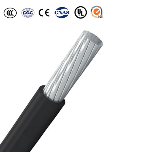
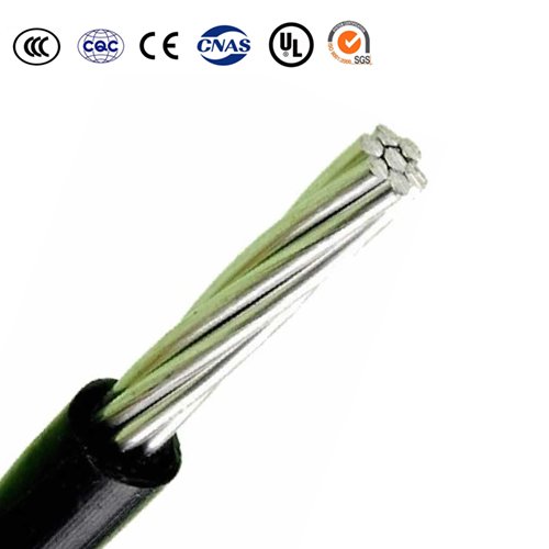
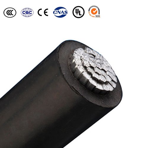
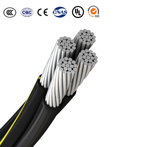
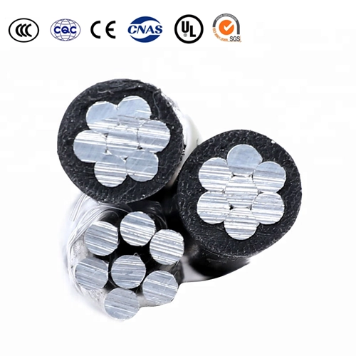
Construction
The conductors are stranded, circular compressed or uncompressed aluminum, copper, aluminum-alloy, ACSR etc., concentrically stranded and covered for PVC in black (type 8) and green(type 16).
Specifications
• BS 6485 PVC-Covered Conductors For Overhead Power Lines
• BS EN 50182 Conductors For overhead lines — Round Wire Concentric Lay Stranded Conductors
• BS 215-1 Aluminum Conductors and Aluminum Conductors,Steel-Reinforced —For Overhead Power Transmission Part 1: Aluminum Stranded Conductors
• BS 215-2 Aluminum Conductors and Aluminum Conductors,Steel-Reinforced —For Overhead Power Transmission Part 2: Aluminum Conductors, Steel-Reinforced
• BS 3242 Aluminum Alloy Stranded Conductors For Overhead Power Transmission
• BS 7884 Copper and Copper-Cadmium Stranded Conductors For Overhead Electric Traction and Power Transmission Systems
Parameter
| Code Word | Nominal cross-sectional area | Stranding and Wire Diameter | Approximate Overall Diameter of Bare Conductor | Maximum Resistance per kilometre at 20 °C | Approximate Breaking Load | Approximate Overall Diameter of Covered Conductor | Approximate Mass per kilometre of Covered Conductor |
| Type 8 | Type 8 | ||||||
| mm² | mm | mm | Ω | kN | mm | kg/km | |
| AAC/PVC | |||||||
| Midge | 22 | 7/2.06 | 6.18 | 1.227 | 3.99 | 8.2 | 100 |
| Aphis | 25 | 3/3.35 | 7.2 | 1.081 | 4.11 | 9.2 | 133 |
| Gnat | 25 | 7/2.21 | 6.63 | 1.066 | 4.59 | 8.8 | 118 |
| Weevil | 30 | 3/3.66 | 7.9 | 0.9082 | 4.86 | 10.1 | 158 |
| Mosquito | 35 | 7/2.59 | 7.77 | 0.7762 | 6.03 | 10.0 | 156 |
| Ladybird | 40 | 7/2.79 | 8.37 | 0.6689 | 6.87 | 10.6 | 177 |
| Ant | 50 | 7/3.10 | 9.30 | 0.5419 | 8.28 | 11.7 | 200 |
| Fly | 60 | 7/3.40 | 10.2 | 0.4505 | 9.90 | 12.4 | 249 |
| Bluebottle | 70 | 7/3.66 | 11.0 | 0.3881 | 11.34 | 13.2 | 285 |
| Earwing | 75 | 7/3.78 | 11.3 | 0.3644 | 11.94 | 13.6 | 302 |
| Grasshopper | 80 | 7/3.91 | 11.7 | 0.3406 | 12.78 | 13.9 | 319 |
| Clegg | 90 | 7/4.17 | 12.5 | 0.2994 | 14.53 | 14.7 | 359 |
| Wasp | 100 | 7/4.39 | 13.17 | 0.2702 | 16.00 | 16.0 | 360 |
| Beetle | 100 | 19/2.67 | 13.4 | 0.2704 | 17.42 | 15.6 | 387 |
| Bee | 125 | 7/4.90 | 14.7 | 0.2169 | 19.94 | 16.9 | 482 |
| Cricket | 150 | 7/5.36 | 16.1 | 0.1813 | 23.85 | 18.3 | 567 |
| Hornet | 150 | 19/3.25 | 16.3 | 0.1825 | 27.70 | 18.5 | 538 |
| Caterpillar | 175 | 19/3.53 | 17.7 | 0.1547 | 28.63 | 19.9 | 646 |
| Chafer | 200 | 19/3.78 | 18.9 | 0.1349 | 32.40 | 21.7 | 690 |
| Spider | 225 | 19/3.99 | 20.0 | 0.1211 | 36.01 | 22.2 | 809 |
| Cockroach | 250 | 19/4.22 | 21.1 | 0.1083 | 40.40 | 23.3 | 900 |
| Butterfly | 300 | 19/4.65 | 23.3 | 0.08916 | 48.70 | 25.5 | 1082 |
| Moth | 350 | 19/5.00 | 25.0 | 0.07711 | 56.37 | 27.2 | 1241 |
| Drone | 350 | 37/3.58 | 25.1 | 0.07741 | 57.45 | 27.3 | 1222 |
| Locust | 400 | 19/5.36 | 26.8 | 0.0671 | 64.73 | 29.0 | 1416 |
| Centipede | 400 | 37/3.78 | 26.5 | 0.06944 | 63.10 | 28.7 | 1353 |
| Maybug | 450 | 37/4.09 | 28.6 | 0.05931 | 74.01 | 30.8 | 1573 |
| Scorpion | 500 | 37/4.27 | 29.9 | 0.05441 | 79.98 | 32.1 | 1706 |
| Cicada | 600 | 37/4.65 | 32.6 | 0.04588 | 94.95 | 34.8 | 2010 |
| Tarantula | 750 | 37/5.23 | 36.6 | 0.03627 | 120.10 | 38.8 | 2519 |
| Nominal cross-sectional area | Stranding and Wire Diameter | Approximate Overall Diameter of Bare Conductor | Maximum Resistance per kilometre at 20 °C | Approximate Breaking Load | Approximate Overall Diameter of Covered Conductor | Approximate Mass per kilometre of Covered Conductor | ||
| Type 8 | Type 16 | Type 8 | Type 16 | |||||
| mm² | mm | mm | Ω | kN | mm | mm | kg | kg |
| CU/PVC | ||||||||
| 14 | 7/1.60 | 4.80 | 1.303 | 5.744 | 6.8 | 8.4 | 160 | 190 |
| 16 | 3/2.65 | 5.70 | 1.106 | 6.590 | 7.7 | 9.3 | 180 | 220 |
| 32 | 3/3.75 | 8.06 | 0.5520 | 12.71 | 10.5 | 12.1 | 350 | 390 |
| 35 | 7/2.50 | 7.50 | 0.5337 | 14.097 | 9.9 | 11.5 | 360 | 400 |
| 70 | 7/3.55 | 10.65 | 0.2646 | 26.88 | 13.5 | 14.7 | 690 | 750 |
| 100 | 7/4.30 | 12.90 | 0.1810 | 37.64 | 15.7 | 16.9 | 990 | 1060 |
| Nominal cross-sectional area | Stranding and Wire Diameter | Approximate Overall Diameter of Bare Conductor | Maximum Resistance per kilometre at 20 °C | Approximate Breaking Load | Approximate Overall Diameter of Covered Conductor | Approximate Mass per kilometre of Covered Conductor |
| Type 16 | Type 16 | |||||
| mm² | mm | mm | Ω | kN | mm | kg |
| COPPER-ALLOY / PVC | ||||||
| 12 | 3/2.30 | 4.95 | 1.780 | 7.20 | 8.2 | 170 |
| 22 | 7/2.00 | 6.00 | 1.011 | 12.94 | 9.6 | 270 |
| 38 | 7/2.60 | 7.80 | 0.5983 | 21.69 | 11.8 | 430 |
| 75 | 7/3.70 | 11.10 | 0.2954 | 40.23 | 15.1 | 810 |
| 125 | 19/2.90 | 14.50 | 0.1784 | 68.75 | 18.5 | 1310 |
| 150 | 19/3.20 | 16.00 | 0.1465 | 82.16 | 20.0 | 1570 |
| Nominal cross-sectional area | Stranding and Wire Diameter | Approximate Overall Diameter of Bare Conductor | Maximum Resistance per kilometre at 20 °C | Approximate Breaking Load | Approximate Overall Diameter of Covered Conductor | Approximate Mass per kilometre of Covered Conductor | |
| Aluminum | Steel | ||||||
| Type 8 | Type 16 | ||||||
| mm² | No./mm | No./mm | mm | Ω | kN | mm | kg |
| ACSR / PVC | |||||||
| 25 | 6/2.36 | 1/2.36 | 7.08 | 1.093 | 9.61 | 10.7 | 190 |
| 50 | 6/3.35 | 1/3.35 | 10.05 | 0.5426 | 18.35 | 14.1 | 330 |
| 100 | 6/4.72 | 7/1.57 | 14.15 | 0.2733 | 32.70 | 18.2 | 550 |
| 150 | 30/2.59 | 7/2.59 | 18.13 | 0.1828 | 69.20 | 22.2 | 920 |
| 150 | 18/3.35 | 1/3.35 | 16.75 | 0.1815 | 35.70 | 20.8 | 680 |
| 175 | 30/2.79 | 7/2.79 | 19.53 | 0.1576 | 79.80 | 23.6 | 1050 |
| 175 | 18/3.61 | 1/3.61 | 18.05 | 0.1563 | 41.10 | 22.1 | 780 |
| 200 | 30/3.00 | 7/3.00 | 21.00 | 0.1363 | 92.25 | 25.0 | 1190 |
| 200 | 18/3.86 | 1/3.86 | 19.30 | 0.1367 | 46.55 | 23.3 | 870 |
| Nominal cross-sectional area | Stranding and Wire Diameter | Approximate Overall Diameter of Bare Conductor | Maximum Resistance per kilometre at 20 °C | Approximate Breaking Load | Approximate Overall Diameter of Covered Conductor | Approximate Mass per kilometre of Covered Conductor |
| Type 16 | Type 16 | |||||
| mm² | mm | mm | Ω | kN | mm | kg |
| AAAC / PVC | ||||||
| 25 | 7/2.34 | 7.02 | 1.094 | 8.44 | 10.6 | 170 |
| 50 | 7/3.30 | 9.90 | 0.5498 | 16.80 | 13.9 | 280 |
| 100 | 7/4.65 | 13.95 | 0.2769 | 33.30 | 18.0 | 470 |
| 150 | 19/3.48 | 17.40 | 0.1830 | 50.65 | 21.4 | 680 |
| 200 | 19/3.76 | 18.80 | 0.1568 | 59.10 | 22.8 | 780 |
PDF Download
PDF Download
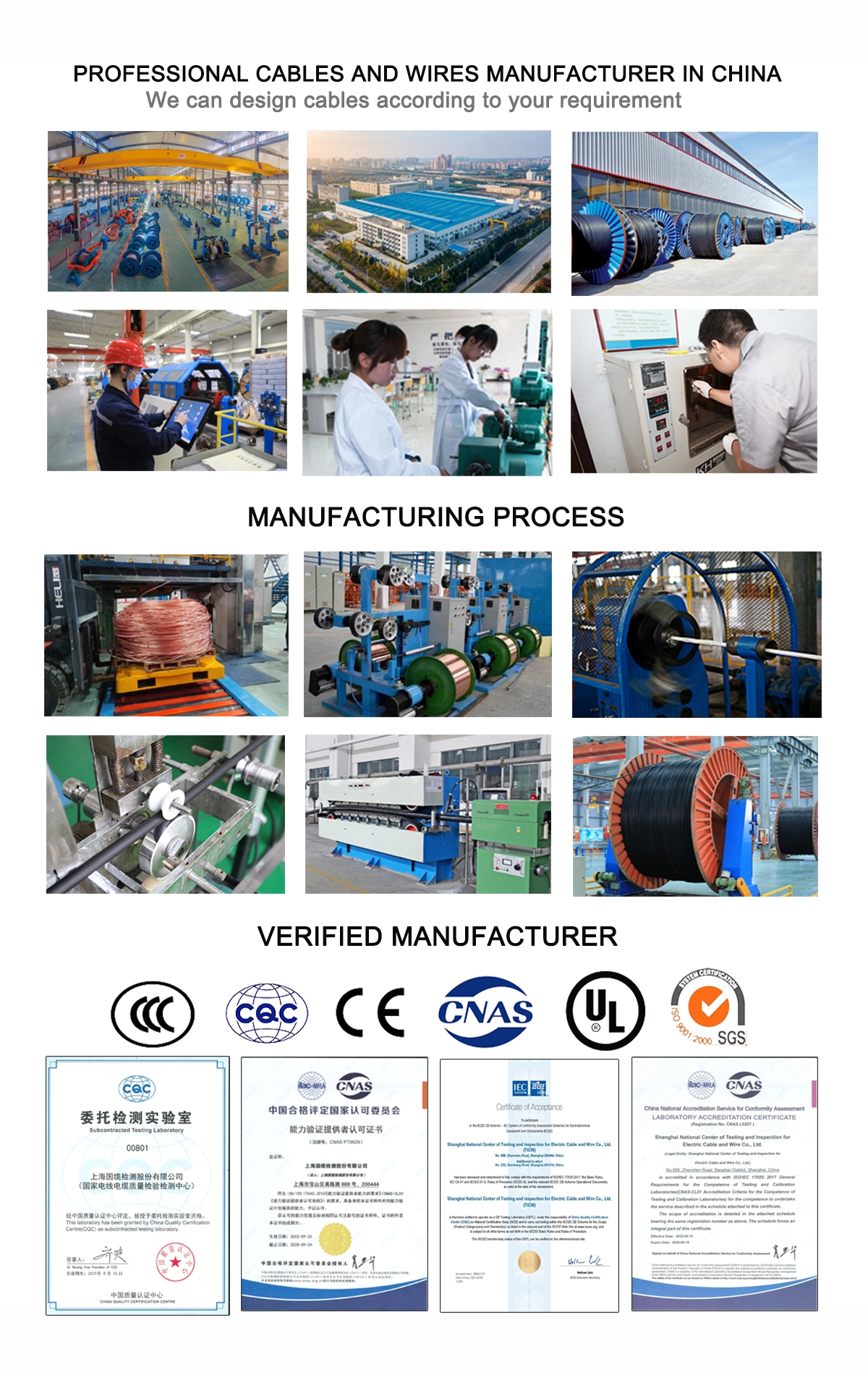
Why Choose Us
Contact Us Immediately
Contact Us
- 24-hour online service
- Own factory processing
Product Category
hot-sale product
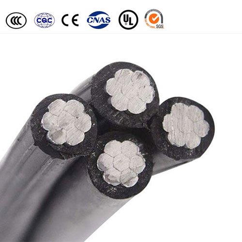
Including 1, 2, 3, 4, 5, 1+1, 2+1, 3+1, 4+1 cores and so on, from 10mm2 to 240mm2 as follows, 10mm2 16mm2 25mm2 35mm2 50mm2 70mm2 95mm2 120mm2 150mm2 185mm2 240m2.
Conductor: 1350-H19 Aluminum conductor, H68 round stranded conpressed(RM) Aluminium Conductor
Insulation: XLPE or PE or PVC, UV-resistant.
Cable Structure: POLYETHYLENE INSULATED
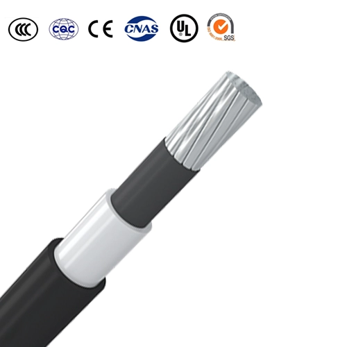
Conductor: Compact stranded hard drawn Aluminium wire.
Conductor Sizes: 35 – 185 mm2
Insulation: Track resistant cross-linked polyethylene (Black)
Application: For used in primary aerial cable on pole.
Cable Torsadé Aluminium; Câble Torsadé Aérien; Câble électrique Aérien
Phase Conductor: Aluminium conductor, round stranded compressed (RM).
Neutral Conductor: Alloy aluminium conductor (AlMgSi), round stranded compressed (RM).
Insulation: XLPE. Load-bearing / neutral core – marked with standard and producers phase core – marked with digits 1, 2, 3.
Assembly: Cores and the neutral, conductor stranded together in right-hand lay, additionally 1, 2 or 3 cores of reduced cross section can be co-stranded.